Prints (0)
-
No Prints Yet
Be the first to upload a Print for this Design!
Description
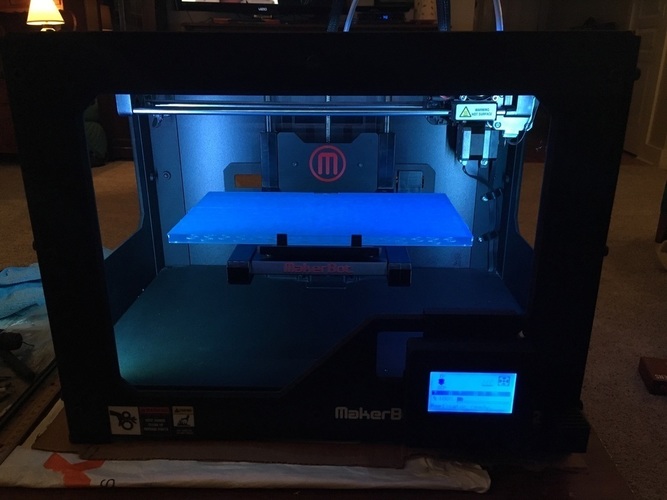
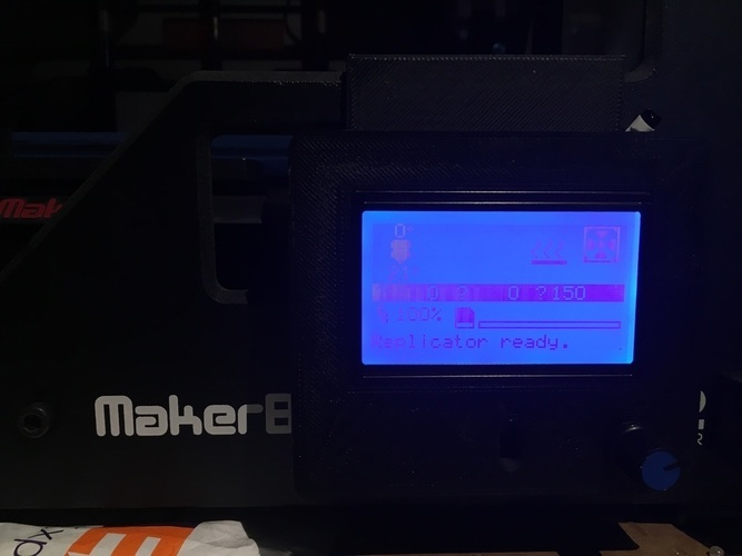
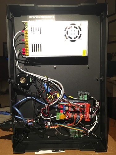
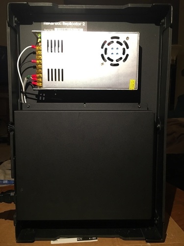
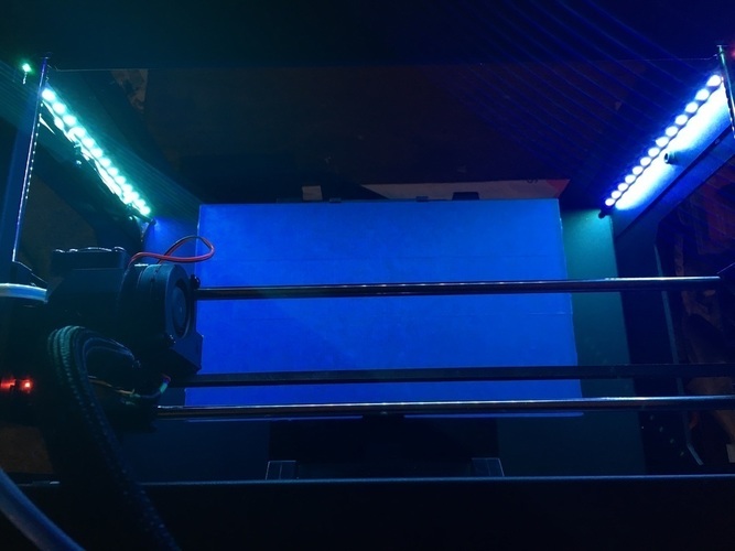
Summary They said that it could not be done, yet here it is! Fix your Makerbot Replicator 2 for $100. I have successfully stripped the Makerbot Replicator 2 of its true self and given it something better! I converted my Makerbot from the original 24V MightyBoard to a 12V Ramps 1.4 Board. It is fully functional and works better than the original (in my opinion). If you are tired of using Makerware, dislike the Makerbot firmware, or have a dead Makerbot that has completely stopped working... this is a proven way to revive your 3D printer and transform it into a stronger machine for around $100! I plan to add new things to this page as I make upgrades to my Makerbot. Please use the comments section if you have any questions. How I Designed This I came up with this idea because I have had a Makerbot Replicator 2 that has been running constantly since I purchased it in 2012. After years for non-stop printing and torture, this machine just died. One day I walked up to it and the screen was blank and all the electronics were dead. I called Makerbot to see how much it would be to replace the internals (the Mightyboard and the LCD screen) and I was quoted around $500 to replace the electronics. Now today, for around $500 I can buy a brand new 3D printer, so there was no way that I was going to buy new Makerbot parts. I’ve never really been a fan of the Makerbot electronics, Makerware, and Firmware because of the way it is a closed system that is not supposed to be tampered with or changed. Therefore I came up with the idea to change it to a Ramps 1.4 system running on custom built Marlin Firmware and Simplify3D slicer. I have searched around on the internet for anything like this, but sadly was unable to find anyone who has done this same thing to a Makerbot. First thing I did was rip out the Makerbot electronics. Now make sure to not throw them away. I took out my Mightyboard, LCD screen, Makerbot heater cartridge, and Makerbot power supply and then listed them on eBay. I ended up selling all of these parts for $300! Using this money I purchased all of the things on the parts list as well as a soldering iron, solder, glue gun, heat shrink wire protectors, electrical tape, and zip ties. From this point, I started building. See the "Instructions" tab for more info. Parts List Parts you need: 12V 30A Power supply $20 https://www.amazon.com/NEWSTYLE-Universal-Regulated-Switching-Computer/dp/B00MAC9MO6/ref=sr_1_1?ie=UTF8&qid=1468378891&sr=8-1&keywords=12+v+30a+power+supply Ramps 1.4 Kit - $30 https://www.amazon.com/OSOYOO-Printer-Controller-Stepper-Heatsink/dp/B0111ZSS2O/ref=sr_1_1?ie=UTF8&qid=1468378924&sr=8-1&keywords=ramps+1.4 External Thermocouple Board v1.0 - $16 http://e3d-online.com/Electrical/Components/External-Thermocouple-Board-v1.0 12V 30W Heater Cartridge - $6 http://e3d-online.com/Electrical/Components/Heater-Cartridge-12v-30w Power Cable - $5 https://www.amazon.com/Prong-Universal-Standard-Connector-Cables/dp/B00F0UO11Y/ref=sr_1_4?s=electronics&ie=UTF8&qid=1468379543&sr=1-4&keywords=standard+usa+power+cord Power Entry Module - $20 https://www.amazon.com/gp/product/B009180J44/ref=oh_aui_detailpage_o07_s00?ie=UTF8&psc=1 Jumper Wires $8 https://www.amazon.com/Honbay%C2%AE-120pcs-Multicolored-Female-Breadboard/dp/B017NEGTXC/ref=sr_1_3?ie=UTF8&qid=1468378989&sr=8-3&keywords=jumper+wires Optional parts: LED Light controller - $6 https://www.amazon.com/dp/B00JRVSO38/ref=sr_ph_1?ie=UTF8&qid=1468379252&sr=sr-1&keywords=led+light+controller LED Light Strip Kit - $28 https://www.amazon.com/LEDwholesalers-Changing-Flexible-Controller-44-button/dp/B0040FJ27S/ref=sr_1_2?ie=UTF8&qid=1468540573&sr=8-2&keywords=led+rbg+light+strip Instructions I am not going to put together a detailed instructions list, but more of an overview of the project. I recommend using reprap.org for help. You can see how I put it all together in the photos. If you are looking into doing this to your Makerbot and have any questions about what I did, please just ask in the comments section. Pre-Build: Rip out original Electronics. This includes the Mightyboard, LCD interface, and heater cartridge (located in hot-end). Make sure to leave all of the original wiring and connections left over from the Mightyboard. I use these to make wiring easier later on. Purchase all the parts on the parts list. Building: Glue the 12V 30A power supply, ramps 1.4 board, and external thermocouple board to the bottom of the Makerbot. It is best to use the location under the bottom panel cover for the electronics so they can be covered up at the end. Using the jumper cables, connect all of the components into their proper places on the Ramps 1.4 board. This includes motors, end stops, drivers, heaters, fans, and the screen. Wire the ramps 1.4 board to the power supply Mount the reprap LCD controller to the front of the 3D printer. There are .STL files you can download in the files section that I designed to hold the LCD controller. Run the ribbon cables through the original hole to the ramps 1.4 board. Also, you can 3D print an SD card holder that will mount next to the controller for card storage. Using the external thermocouple board, connect the thermocouple cables to the external board and connect the external board to the ramps 1.4 board. You can see this in the picture mounted above the ramps 1.4 board. There is a more detailed explanation of how to do this here: http://reprap.org/wiki/ExtThermoCouple_1.0 Install the heater cartridge into the hot-end. Note that the heater cartridge that I used is smaller in diameter than the original Makerbot heater cartridge and it fits in differently. A new heater cartridge is required for this build because the Makerbot originally runs off of a 24V system and uses a 24V 40W heater cartridge. This build uses a 12V system and a 12V 30W heater cartridge. If you try to heat up the 24V heater on the 12V system it takes about 15 minutes to heat it up to 150C and it will never reach the needed temperature to melt plastic. Optional: wire LED light board. I purchased the LED controller on Amazon. It came with a little plug in receiver and remote. I broke open the receiver open to get to the board. I soldered power wires and the RGBW wires to it. After it was all connected I then had control of the Makerbot's LED lights with the remote control. You can see this in the picture mounted below the ramps 1.4 board Remove the old LED light strip from the top of the Makerbot and install a new RBG light strip in the same place. I chose to add LED lights on the top, left, and right of the printer to make it brighter. My Makerbot LED lights only shined red, so I put in the new LED lights so I would have full control of color and patterns. Firmware: I build my own custom version of marlin firmware. You can download a copy of marlin and edit it in Arduino IDE. https://github.com/MarlinFirmware/Marlin Once you have your firmware done, you can load it to the board using a USB cable. If you would like to try the version of marlin that I made, you can download it in the files section. Use it at your own risk. Calibrating: After the firmware is built, it will need testing. Make sure everything moves properly and that the motors are set to the proper steps per mm and things like that. Do a few test prints. This will require a lot of trial and error. I got is done in about and hour. Printing: You have now successfully competed the conversion to Ramps 1.4. Please share on this page and feel free to add any new things you may have discovered. Resources: I utilized reprap.org for the majority of this project. They have many helpful things about ramps 1.4, marlin, wiring diagrams, troubleshooting, and anything else you may have trouble with. I will put some helpful links below. http://reprap.org/wiki/Main_Page http://reprap.org/wiki/RAMPS_1.4 http://reprap.org/wiki/Marlin http://reprap.org/wiki/ExtThermo
Comments