Prints (0)
-
No Prints Yet
Be the first to upload a Print for this Design!
Description
DESIGN PROCESS
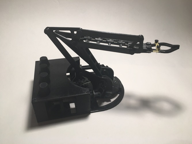
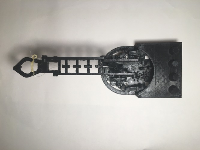
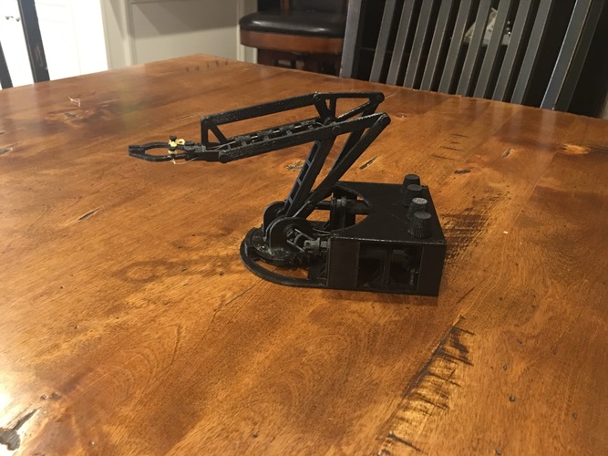
I have always been intrigued by robot arms and the different mechanisms that allow them to work. I really wanted to pursue the challenge of designing a small, desktop sized robot arm that could be controlled without servos or stepper motors.
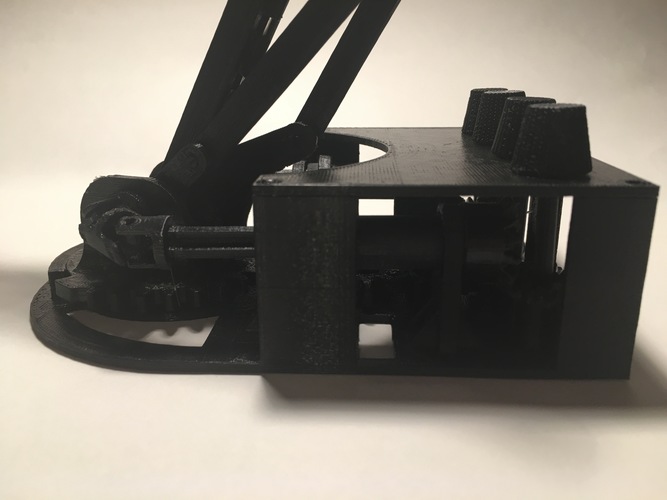
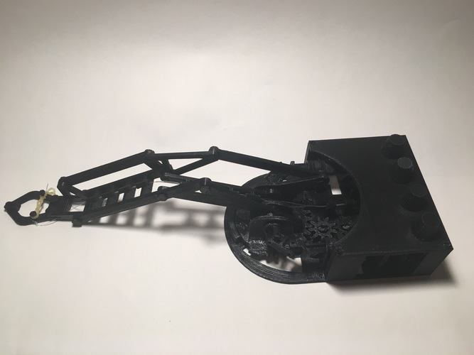
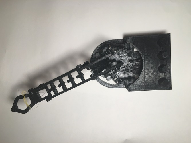
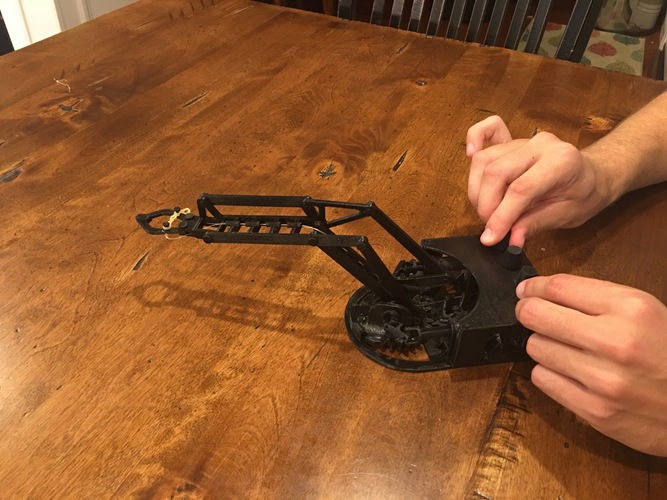
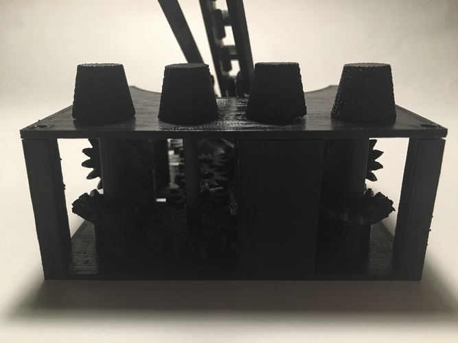
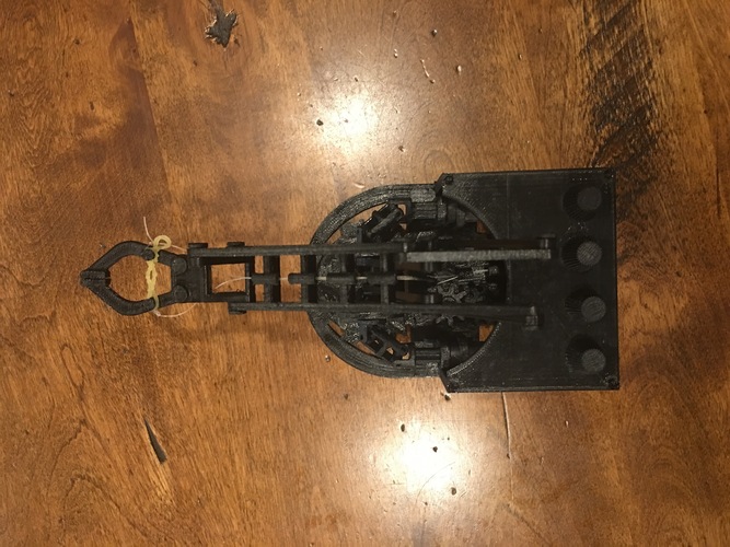
After researching various types of robot arms, I discovered that all of them were utilizing servos or motors in the arm themselves. Basically, I found that to build a robot arm you needed some of the motors housed in the base of the arm that will rotate. My vision when I first started to design the arm, was a small 3D printed arm with a number of knobs on the base that would control it. No servos, no stepper motors, no electricity. I really wanted to test the limits of 3D printing and my mechanical knowledge to design a functional, fully mechanical desktop arm.
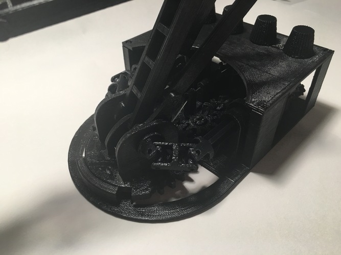
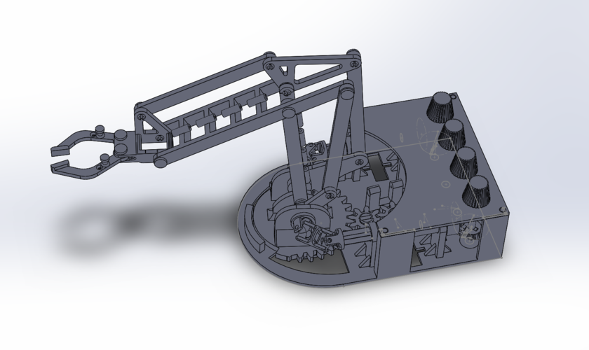
The biggest challenge was designing the base of the arm that would allow the knobs to turn parts of the arm that would rotate with the base of the robot as it turned. Initially I thought I would be able to get away with only using universal joints for this, but I soon found out this wouldn't work alone, because as the base rotates the connection would move further or closer to the base. I ended up using telescoping tubes with a cross intersection that would allow the axle to rotate, change lengths, and change direction. I went through a number of iterations to design universal joints that would work with my design. My final design allows each joint to bend up to 64 degrees while still transmitting the rotation.
This project was designed in SolidWorks, and I am very happy with how it turned out. I learned a lot along the way, and I will be going forth and making future improvements to my design. I have since added some bike wax lubricant to the joints and it moves a lot smoother now. It can pickup and move small objects around, success!
You can see a video of it in action here!
SETTINGS
Machine: Makerbot Replicator z18
Material: PLA
Layer Height: 0.2 mm
Infill: 50 %
Support: No support up to 2 mm
Rafts: Yes
PRINTING
Print the following parts, in the correct orientation, and correct amount. Note some of the parts are printed horizontally to increase strength.
lower_base x1 - flat
spur_gear_18_9 x3 - flat
spur_gear_24_12 x1 - flat
spur_gear_60_30 x1 - flat
bevel_gear_20_15_gear1 x2 - flat
bevel_gear_20_15_gear2 x2 - flat
U_joint1 x2 - lying horizontally with the opening facing up and holes parallel to floor
U_joint2 x2 - lying horizontally with the opening facing up and holes parallel to floor
U_joint3 x2 - lying horizontally with the opening facing up and holes parallel to floor
U_joint_cross x4 - flat
telescoping_tube1 x2 - vertically
right_arm_ext1 x3 - flat
right_arm_ext2 x1 - flat
right_arm_ext3 x31 - flat
left_arm_ext1 x1 - flat
left_arm_ext3 x1 - flat
pin x12 - horizontally
pin2 x1 - horizontally
arm_ext_spacer x1 - horizontally
fishing_wire_spool x1 - flat
gripper1 x1 - flat
claw1 x1 - flat
claw2 x1 - flat
top_base x1 - flat
knob1 x1 - lying horizontally, rod is parallel to floor
knob2 x1 - lying horizontally, rod is parallel to floor
knob3 x1 - lying horizontally, rod is parallel to floor
knob4 x1 - lying horizontally, rod is parallel to floor
ASSEMBLY INSTRUCTIONS
Please watch the assembly video here for detailed instructions on how to assemble the arm.
Thanks for checking it out!
Comments