Prints (0)
-
No Prints Yet
Be the first to upload a Print for this Design!
Description
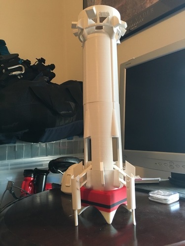
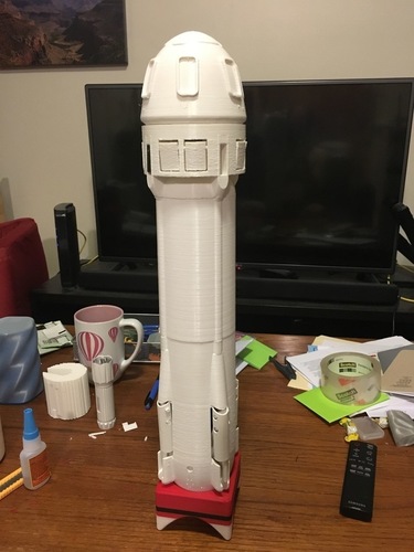
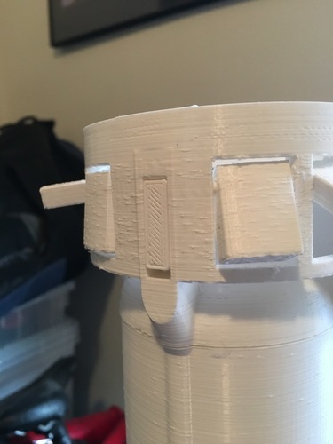
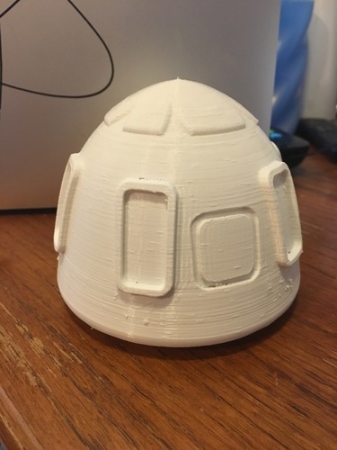
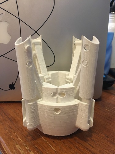
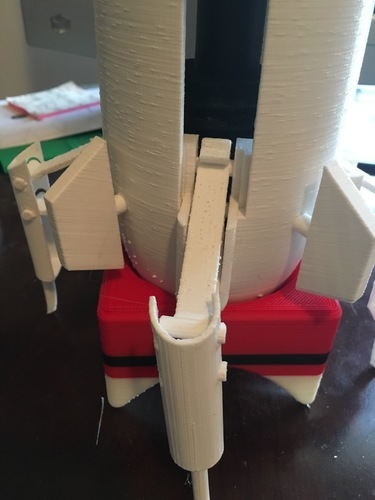
Summary This is a model of Blue Origin's New Shepard rocket, one of the first rockets to successfully land and relaunch it's first stage. The model has the following features:
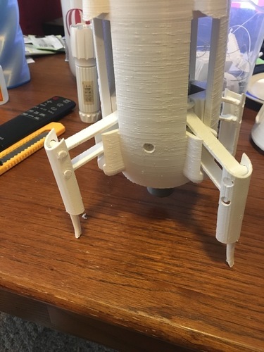
•Rotate the engine to raise and lower the landing legs
•Removable crew capsule
•Drag flaps that can be opened and closed
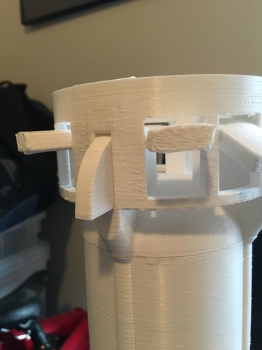
•Upper fins that fold in for launch and out for landing
•Rotatable lower fins
•Display stand
Images of the actual rocket can be found here: https://www.blueorigin.com/gallery
Printing Notes: Be very careful when removing support material, especially from the lower stage as it is easy to snap the leg struts before the landing legs are attached. Grasp the landing struts by the hinge when first rotating them to avoid snapping them.
Landing Leg Mechanism:
Landing leg mechanism: the files have been since modified prevent the jamming seen in the video Assembly instructions Images for each step below.
Assembly instructions:( See images for guides to assembly)
1. Attach the landing legs to the lower stage by sliding the struts into one side of the leg and snapping the other side into place.
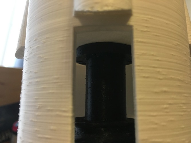
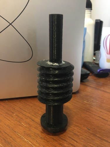
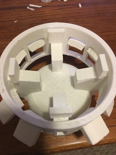
2. With the legs in the lowered position, screw the gear about half way into the lower stage with the smaller diameter end down. Glue the engine onto the gear post sticking through the bottom of the lower stage. (Super glue works well)
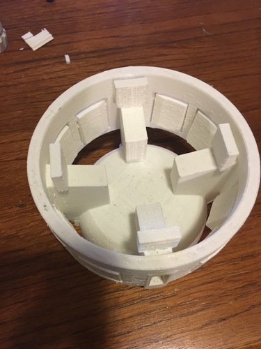
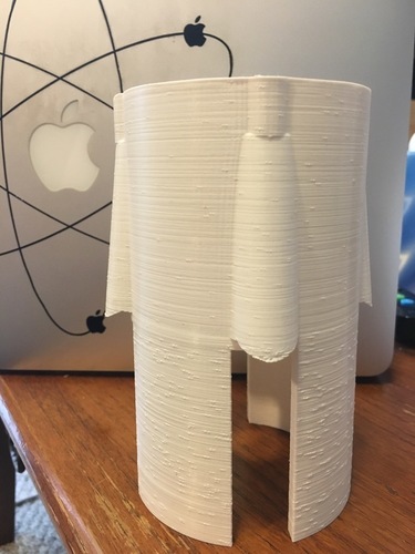
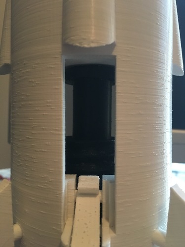
3. Place the middle stage on top of the lower stage with the slots facing down and lined up with the landing legs. Turn the engine so that the wide part at the top of the gear is resting against the plate in the middle of the middle stage.
4. Place some glue on the inside of the gear cap and place it on top of the gear through the top of the middle stage. Once the glue dries you should be able to twist the engine to raise and lower the landing gear. **DO NOT glue the cap to the middle stage. It needs to be able to rotate freely when the gear is turned.
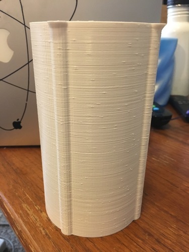
5. Glue the upper stage onto the middle stage, lining up the ridges on the sides of the rocket.
6. Glue the ring adaptor to the top of the upper stage.
7. Insert the ring fins into the slots on the ring adaptor with the longer flat end on the bottom.
8. Insert the lower fins into the holes between the legs on the lower stage.
Comments