
Prints (0)
-
No Prints Yet
Be the first to upload a Print for this Design!
Description
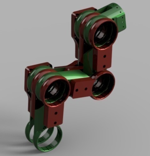
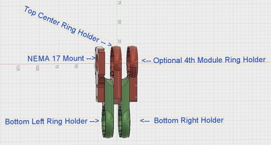
Summary Updates! 3/26/17- Uploaded Arduino sketch that i have been controlling this with. I have improved this by making it do calculations when the joint has arrived at a point, and calculating all the angles it has to move to before it begins moving. the homing is done by just moving the joint to its max left position then max right so the stepper will skip steps until its centered. i used 1/4 stepping on my stepper driver for this. 3/18/17- Revised Rotating Base, http://www.thingiverse.com/thing:2186716 3/15/17- New Youtube Video: https://www.youtube.com/watch?v=_ZqThKUGIBc&feature=youtu.be 3/14/17- Uploaded the Arduino Program that I'm using to control this. it uses inverse kinematics to determine the position of J3 from XYZ. 3/12/17- V3 parts - Chamfered the hole that the pins fit into so there isn't extra material from bridging that needs removal. 3/9/17- V2 - Fixed issues with too much clearance between the ring gears and ring holders. Made all of the ring holders .1mm smaller, leaving .1 of clearance between the ring gear and ring holder. I Included the Fusion 360 Project with this :) The Gearbox (43.33 :1) for use with this joint is a different "thing", heres a link http://www.thingiverse.com/thing:2101218 The gearbox is absolutely necessary for this joint because it not only drives the joint but it also works off the concept of Emmets "Gear Bearing" and provides a bearing for the hinge joint, this is the ONLY Gearbox that will work with this, I suggest using the "one piece sun gear" and the "4 Module planet gears" for the joints that are under the most stress, its also a good idea to print the #2 sun gear and use that in the 4th module. Most of the pieces in the picture of the actual assembly are prints from the prototyping stages, the design i am uploading now is the part of the joint printed in white.. This Thing is a redesign of http://www.thingiverse.com/thing:2105057 This version requires 2X - 4mm thread bolts or 2X- 6/32's This gearbox and joint setup has very little backlash, maybe 1 degree when the gears are printed correctly. Running the gearbox without it pressed into the arm is a good way to wear it in so it doesn't rob torque from your stepper, but it can also take the the planet gears out of alignment if the rings open up and skip a gear. if the gears aren't arranged as pictured above the gearbox will wear itself out rather quickly. I designed the gearbox with an optional 4th ring and 4 module planet gears to accommodate that, I highly recommend using that setup. For that, you will also need to print out the Optional 4th Module Holder.STL file from this "thing" This setup will give the joint a lot more support against side to side play and will also reduce backlash. all of the parts are stackable, this design is fully compatible with old design and the gearbox in the link is the same one for both designs This arm rotates 230 degrees before colliding with itself in the cad program but it is actually more like 229 degrees real life Feel Free to Create your own joints and attachment for this project ;) Oh yeah, If you print this, would you kindly post a make with a picture or video? Please and thank you!
Comments