

Prints (0)
-
No Prints Yet
Be the first to upload a Print for this Design!
Description
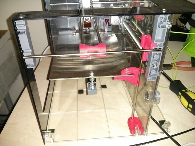
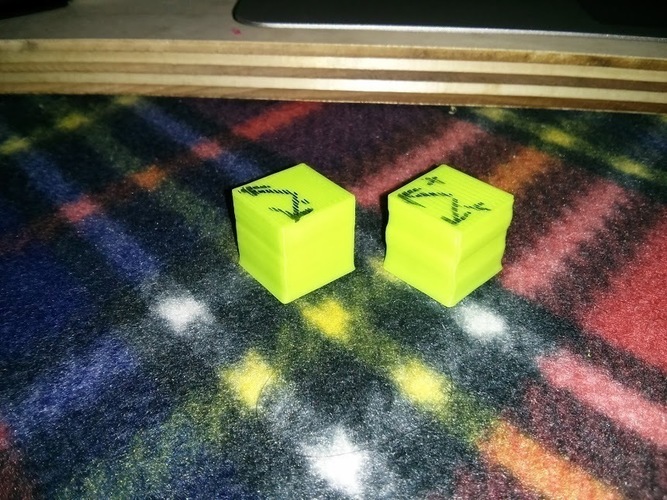
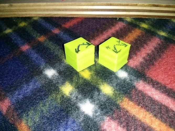
SummaryI wanted to come up with a solution to the Makibox Z wobble that is found in every printer that they make (that's what you get from a $300 printer). After analyzing their design, I found that the Y axis end supports were redundant, allowing the ability to remove and use one of the metal rods. By using this rod and a few 3D printed parts, I was able to greatly reduce the amount of wobble in the X axis caused by the Z lead screw moving the table in and out. Pictures show the final assembly, and a Before and After picture, with the After on the left, and before on the right. Large improvements can be seen in the X axis wobble, and slight improvement in the Y axis. I've gone through several iterations of the Z_stabalizer_Table part, and will likely change yet again. V7 uses a slight clamping force with friction to hold onto the table, which is probably lose it's strength over repeated heat-cooling cycles, but has the best sliding along the rail. Once it loses it's strength, it should be perfect for sliding, and can be held to the table with some high temperature silicone or similar non-rigid adhesive. V6 didn't clamp, but held rigidly and had more friction that I would like. Using a grease on this rod would probably allow V6 to work just as well. I've uploaded IGES versions of the final parts for others to import and modify, as the original parts were designed in Solidworks 2014. InstructionsI printed all parts on a Replicator 2, 0.1mm layers, 3 shells, 30% infill. First, remove the panel at the end of the printer so that you can see the far end of the guide rails at the end of the Y axis. Remove the two small grey plastic cylindrical end guides at the end of the rods, the plastic and metal end clamp that span the two Y axis rods, and the metal rods that are used for the Y axis support. Second, print the pom_support_rod_endguide and place one of the metal rods into it. Slip this printed part onto the two Y axis rods, placing the metal rod into the lower slot of where it was removed from. Third, print the Z_stabalizer_Base and place it on the base of the printer, so that it straddles the nub that is used for screwing in the end panel. Fourth, print the Z_stabalizer_Top and insert it around the top X axis support rail at the mid point of the printer, NOT right at the end where it enters the plastic support part. You need some additional clearance to insert it. Then slide it down to go onto the grey plastic corner support part, flexing the arm slightly so that it can fit around and snap into the upper groove where the metal rod previously sat. Fifth, insert the spare metal rod into the top rail and slide (push and force) it directly down until it enters the bottom support printed part. You can alternatively snap it into the top part, but it's just as easy to slide it in. Sixth, attach the Z_stabalizer_Table part to the table, and then snap it onto the metal rod. V7 seemed to slide the best as it was not over constraining the system, however, I'm not sure it will hold rigidly enough over time as it's in constant contact with the heated bed. V6 constrains the system perfectly, but results in too much friction while it slides which could cause some problems. I've posted it so that others might be able to use and improve upon it. After printing with it, I have found that the original strength of the V7 clamp was not the same as it was, but it still holds it tight enough. I will be putting some high temperature gasket silicone to hold it in position, as it looks like it has slightly deformed where the pressure was the greatest, but it now slides with no friction at all. This was printed in Makerbot PLA and the table was 110C for the first layer and warm-up and then 90C for the rest of the printing which caused the slight deformation. It still works without the silicone, but I think that will provide rigidity when printing, but flexibility with the heating and cooling cycling. Super glue (CA) would hold initially, but through the thermal cycling, would break it's bond, so something with some flex would be better.
Comments