Prints (0)
-
No Prints Yet
Be the first to upload a Print for this Design!
Description
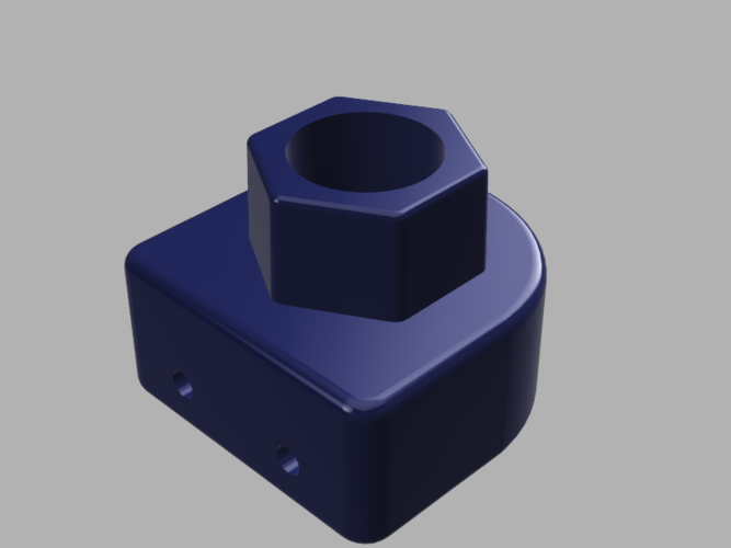
For people who experience Z Axis ribbing and want a cheaper alternative to the "Official" Robo3D Z Axis upgrade, here is what you need. Print two copies of the model presented here. It is an adapter that will take a brass leadscrew nut and adapt it to fit the hexagon opening of the Robo3D X Idler. There is a very slight taper to the hex to help minimize backlash. With the adapter in place there is no loss of Z axis build height and the Auto-level still functions as normal.
Although it is designed to be a pressure fit on the leadscrew nut, you should also use four M3 x 8 mm (#4 x 3/8" equivalent) self tapping screws to secure the nut in place.
At the same time this adapter also replaces the Auto-level Stabilizers that are used to attach the Z Axis leveling microswitches. Use two M2.5 x 8 mm (#2 x 3/8" equivalent) self tapping screws to attach the microswitches to the adapter.
Additionally you should also replace the flexible motor shaft couplings with solid couplings. You will need two couplings that are designed with a 5 mm bore on one end and an 8 mm bore on the other. Picture for illustration purposes only
In addition you will also need two pieces of TR8*8 Leadscrews and accompanying Leadscrew Nuts. Length should be about 350 - 300 mm.
This was created to provide a readily available alternative to the Robo Upgrade and to make installation as simple as possible. You do not need to remove any wiring or stepper motors in this process. Disassembly of your Robo is kept to a minimum. Also the chances are reduced of receiving a bent lead screw without the integrated stepper.
Multiple versions of the source files are included if you need to modify the dimensions slightly (STEP, SAT & SMT).
Print SettingsPrinter Brand:
Robo 3D
Printer:
R1 ABS + PLA Model
Rafts:
Doesn't Matter
Supports:
Doesn't Matter
Resolution:
Any
Infill:
Any
Notes:
This can basically be printed with any amount of infill. It should also be printed with no supports. I would suggest using a filament that has a lower coefficient of friction such as PETG or Nylon.
Verify that all measurements are correct, as this is a model designed to be pressure fit together. Proper extruder calibration should be done prior to printing these parts.
Post-PrintingRequired Hardware
- 2 - TR8*8 Lead Screw and Nut Assemblies 300 - 350 mm length
- 2 - Solid Motor Couplings w/ 5 mm and 8 mm bores
- 4 - M2.5 x 8 mm Self-Tapping Machine Screws
- 8 - M3 x 8 mm Self-Tapping Machine Screws (Optional)
Firmware Modification Please note that the following entry in Marlin Configuration.h must be changed: #define DEFAULT_AXIS_STEPS_PER_UNIT {80,80,2560,723.38} The value of the third parameter (2650) needs to be changed to the following: #define DEFAULT_AXIS_STEPS_PER_UNIT {80,80,400,723.38}
The value listed above is for the most commonly available lead screw TR8*8. One complete rotation moves the Z axis 8 mm. If you have a lead screw with any other movement dimension, please use the Prusa calculators to find the appropriate value for your particular needs. The calculator is located at the following link, Reprap lead screw step calculator
Revisions17 Sept 2016, increased taper on hexagonal section to make sliding into X-Axis bracket easier. moved micro-switches up an additional 0.1 mm to ensure engagement.
14 Dec 2015, moved the screw holes for the microswitch up 0.2 mm to make sure the top of the switch sits above the level of the flattened area. This change was to insure that the switch is depressed completely when in its normal position.
25 Nov 2015, increased the taper a bit to make sliding on easier. Please print then measure. If it doesn't fit snugly when inserted, then reprint increasing the scale just a bit. Now included IGES and Fusion 360 backup files.
Additional InformationAdditional information may be found at the Robo3D forums located at http://community.robo3d.com/index.php
Comments