Prints (0)
-
No Prints Yet
Be the first to upload a Print for this Design!
Description
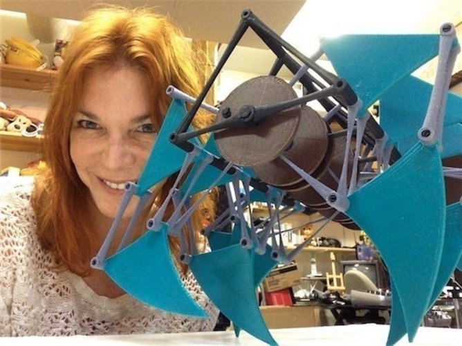
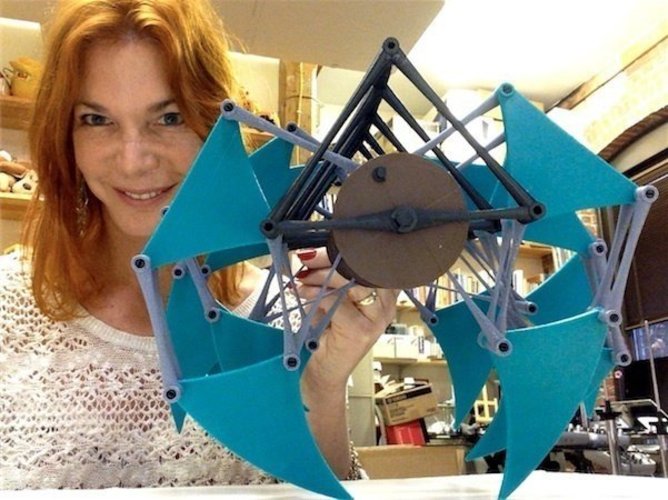
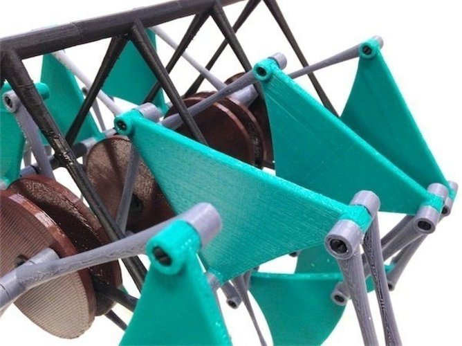
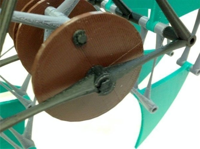
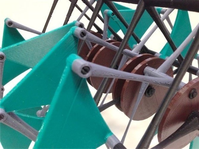
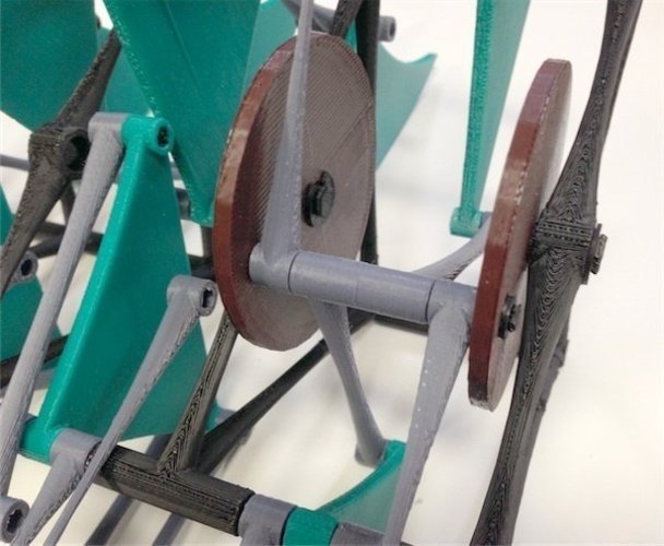
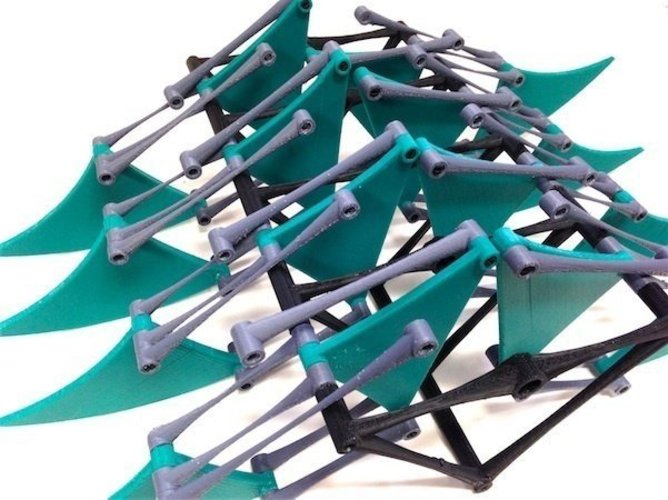
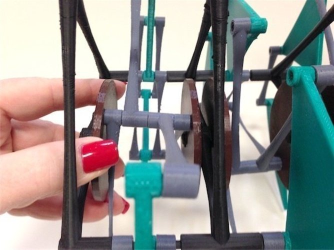
SummaryAfter some tweaking of GolanHertz's original model (converted to STL's by cyclone) I've arrived at a version of this which is assemble-able and reasonably robust. My motivations were to honor the genius of Theo Jansen http://en.wikipedia.org/wiki/Theo_Jansen and to disprove cyclone's assertion that the model is unprintable :) It's never going to walk very well due to the floppiness of the crankpins (see the last photo) but the mechanism does work, it was a good printing challenge, and the end result is a great sculpture. See the "Instructions" tab for details.InstructionsAll parts have been scaled to 90% of the original in order to fit the build volume of the Up/Afinia printer. ANY PART NOT INCLUDED HERE MUST BE SCALED FROM THE ORIGINAL IN ORDER TO BE COMPATIBLE WITH THE NEW PARTS. I printed all parts in ABS except the wheels, which had severe warpage and splitting problems. For these I used Colorfabb PLA from http://www.printedsolid.com/, which has PHA added for flexibility and ease of printing. Colorfabb would be good for the legs and triangles, too, but I'd already printed these in ABS and they were OK, albeit with a bit of splitting in the legs (gives it an organic feel :) The biggest assembly issue with GolanHertz's original is the fit of the snap-in shafts. They don't fit the bushings as designed. Rather than scale the shafts down or enlarge the holes in the STLs, I elected to drill out the bushings (not in small part because I'd already printed everything at that point). All shaft bushings, including those in the main frame, should be drilled out with a 4.3mm bit. This has the side benefit of ensuring that the holes are smooth and round. Even after enlarging the bushings, the snap-in shafts ("connectors" in the original) still don't work, because when compressed, the head diameter in one direction doesn't change. In order to fix this I snipped off the "sides" of one of the snap-in heads on each shaft, perpendicular to the slot. Snip just enough so that you can push (it takes a bit of force) the head through the bushing. If you snip too much, the snap-head won't hold well. You only need to snip one head of each shaft - leave the other one intact for maximum holding power. Once trimmed, they do work well in most locations, and usually snap in with a satisfying "click". This could certainly be done in the STLs, but I'd already printed the parts and snipping was faster. The splined crankshafts of the original are problematic; I replaced them with hex shafts, which are stronger and use an easier-to-print hex hole in the cranks ("wheels"). I enlarged the "diameter" of these hex shafts in order to fit the main crankshaft bushings more snugly. Also, the original had only one length of crankshaft; shorter ones are needed for the two ends, which I've provided. The biggest design flaw is in the crankpins (snap-in "connector d" in the original design). There is no way these can be strong enough to transmit the required torque without popping out if a snap-in connector is used. I changed these to a retaining-ring style to be consistent with the rest of the design aesthetic and increased their diameter to 5mm for a little bit of added strength. It now holds together, but they still flex too much for real walking action unless you carefully drive both ends of the crankshaft. To accommodate the larger crankpin, I enlarged the holes in the wheels, but I didn't bother to go back and revise the STLs of the linkages that they pass through. You need to drill out each bushing through which the crankpins pass. This means one end of each dogleg linkage (the dogleg end) and also one end of each "longskinny" linkage. Use a 5mm drill bit. Make sure to drill the end of the longskinny linkage that does NOT have a counterbore recess! The recessed end needs to go where a snap-in shaft attaches it to a leg. See assembly notes below. The two very long shafts that run the length of the machine in the lower frame bushings are obviously not printable on an Afinia, so I made smaller shafts (one per crank section) that I call "elbow shafts". These are a snug but movable fit inside the frame bushings and can be installed one at a time while putting the thing together, which is kind of handy. The main frame was sectioned to fit in the printer's build volume. The sections are held together by the "frame pegs". After drilling the shaft bushings to 4.3mm, glue the frame pieces together with the pegs while using the "elbow shafts" to temporarily align the sections. There is no really easy way to assemble this Thing. I think the easiest might be with the frame upside-down as shown in one of the photos. Assemble all the linkages, triangles, and feet to the frame before installing the cranks (wheels) and crankshafts, which go in last. In GolanHertz's assembled STL you can't see where one part ends and another begins, which makes things more difficult; hopefully my photos will be helpful in that respect. IMPORTANT: many/most linkages are NOT symmetrical - they have to go in a specific orientation. The thing to remember is that in every case where a snap-in shaft is used, the head of the snap-in MUST fit into a "counterbored" recess in the part. If you install a linkage backwards so that the head rests against a flush surface instead of a in a recess, the length will be wrong and it won't snap in or hold. This is true not only of the linkages, but the triangles too, which have a recess where they connect to the dogleg linkages. Whe
Comments