


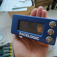


To assemble the dashboard you need
-12 mm metall buttons X3
-Nextion 3.5 Display
-Arduino pro micro
-WS2812b LEDS X2
nuts brass and screws m2 and m3
The connection WS2812b is made sequentially, each led has a plus, minus, incoming and outgoing contact.
The Arduino pro micro is used for control in bridge mode. How to flash, there is information on the SimHub forum.
https://github.com/SHWotever/S...
Connected according to the scheme
GND => GND
VCC => 5V
RX1 => TX
TX0 => RX
PIN6=> Input pin of 1 led.
It is also highly desirable to install the jumper j1 by soldering contacts.
String responsible for the number of LEDs WS2812B_RGBLEDCOUNT 2
Short demo video
Link to the archive with a map of LEDs and a template for nextion will be sent to the mail. To write on [email protected]
Group with ready-made devices https://vk.com/glcustoms
Loading prints...
Racelogic vBox Laptimer
Creative Commons Attribution-NonCommercial-NoDerivatives
You can download and share as long as you credit the creator, but you cannot change the material or use it for commercial purposes.
 Licensed under CC BY-NC-ND

Loading comments...